
- 533 Westover Ln. ~ Pleasant Hill,
CA 94523
- voice/fax 925-256-1444 email:george@kamburoff.com
-
-
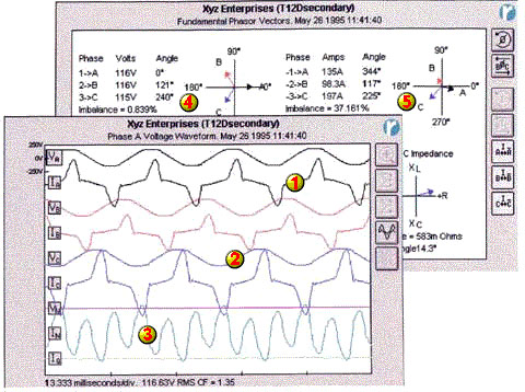
- Shown below are voltage and current graphs
of a transformer serving an office building in Silicon Valley.
Although this is an extrems case, these conditions are common
in today's office environments.
-
- Just click on the numbers on these graphs
to see what effects these conditions might have on your electrical
system and office equipment.
- 533 Westover Ln. ~ Pleasant Hill,
CA 94523
- voice/fax 925-256-1444 email:george@kamburoff.com
- ©Copyright 2000 All rights reserved. Reproduction
of all or part prohibi
1)
These are currents in a transformer feeding standard electronic
equipment. Notice how they crest at the top. These peaks can cause
significant heat in transformers and circuit resistances. Currents
with high crests create voltage drops in the wire to wire proportional
to their height. These peaks also create heat in transformers
and circuit resistances to the square of their peak. This causes
stresses on the electrical system and your equipment, resulting
in shorter lifetimes. These currents are high in third and fifth
harmonics, which produce other problems for the equipment and
electrical system.
TOP
2)
This is the voltage fed into the circuits. Notice how this voltage
sine wave is flattened at top and bottom from drawing the high-peaked
currents discussed above through the transformer and circuit components.
These distorted voltage waves are high in fifth harmonics, which
cause problems forelectric motors and other equipment.
TOP
3) This
Neutral current is the sum of all three of the phase currents.
Notice it is larger than any of the individual phase currents.
These currents do not cancel when they have high peaks, such as
those from office loads and electronic ballasts. This resultant
current is mostly third harmonic (180 Hz), further heating transformers
and wires with its high peaks and frequency. Overheated Neutrals
have caused fires in the walls and partitions of offices, as older
equipment is replaced by computers, fax machines, and other electronic
equipment.
TOP
4)
These arrows are Phase Voltage vectors, showing voltage magnitude
(length) and phase angle (arrow direction). It is evident here
that there are low input voltages to the transformer. This means
the system may be overloaded, or transformers should be checked
for load and the appropriate tap. Low voltages cause motors to
draw excessive current.
TOP
5)
These Current Vectors display high load current imbalances. The
imbalances are the result of poor load management, and result
in the inefficient use of resources. These conditions stress transformers
and other components in the electrical system, and can cause voltage
imbalances, which produce significant heat in three-phase motors.
TOP
- 533 Westover Ln. ~ Pleasant Hill,
CA 94523
- voice/fax 510-256-1444 email:gkam@pacbell.net www.kamburoff.com
- ©Copyright 1998 All rights reserved. Reproduction
of all or part prohibited without express consent.
- Webmaster mailto:jrounkle@pacbell.net